Solid section concept
Carbon fiber rod
Defined by solid diameter and finished length. It is relevant where the buyer specifically requires a solid section; available construction and manufacturing feasibility require confirmation.
CFRP linear components for OEM projects
Custom carbon fiber rods, hollow tubes and linear composite components for robotics, surveying equipment, UAV structures and industrial OEM projects.
Available rod, tube, construction and interface options are reviewed according to the drawing, dimensions, load direction, connection design and order requirements.
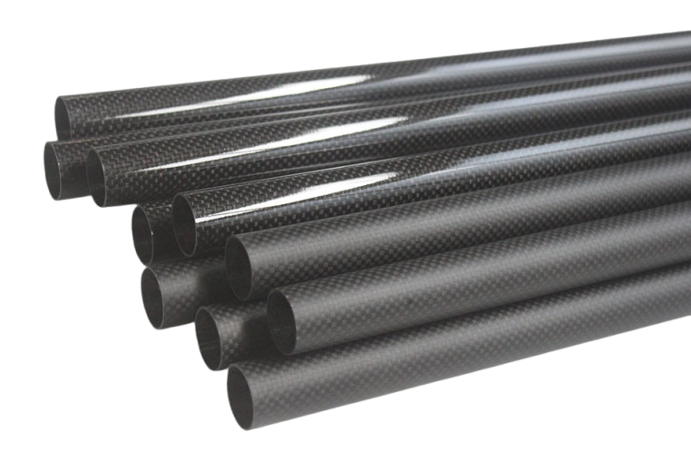
This page covers rod, tube, cut-length and drawing-defined linear component requirements. Buyers should identify the required cross-section, finished geometry and connection design rather than start from a generic product name.
Final structure depends on dimensions, load direction, interfaces, manufacturing review and order requirements. These are components for buyer-designed equipment, not claims that Aero supplies complete robots, surveying instruments or other finished systems.
These terms describe different product or assembly concepts. No unsupported numerical comparison is needed to define the inquiry.
Solid section concept
Defined by solid diameter and finished length. It is relevant where the buyer specifically requires a solid section; available construction and manufacturing feasibility require confirmation.
Hollow section
Defined by OD, ID or wall thickness, and length. It may be selected where a hollow section and lower component mass are preferred, subject to load and interface review.
Application or assembly term
Describes a component used in a pole or support assembly. It does not automatically imply a complete telescopic pole, locking mechanism or finished surveying system.
Each category starts with buyer-defined geometry and ends with technical confirmation of the feasible product route.
Specify solid diameter, length, load direction, end condition and application. Construction and production feasibility require confirmation.
Specify OD, ID or wall thickness, length, load context, surface and connection method. The official image on this page supports this visible product category.
Specify finished length, end condition, tolerance priority, quantity and whether further customer-side assembly is planned.
Provide end geometry, alignment, adapter, insert, bonding or mechanical-interface requirements on the drawing.
Define cross-section, center-to-center geometry, connections, load direction and the interfaces controlled by the buyer's assembly.
State whether the part is a shaft, extension member, antenna support or other component. Complete systems and mechanisms require separate scope confirmation.
Specification confirmation required
No fabricated diameter, wall, length, straightness or tolerance range is published.
Construction affects directional behavior, appearance and the feasible manufacturing route, but visual weave alone does not define the internal structure.
Provide axial, bending, torsional, impact and handling context so construction assumptions can be reviewed around the component's actual role.
A woven-looking surface does not prove a specific internal reinforcement or manufacturing method. Do not infer pultruded, roll-wrapped, UD or hybrid construction from appearance.
Identify visible areas, clamp or bonding zones, handling sensitivity, outdoor exposure and any cosmetic expectation for project confirmation.
Separate the requested feature from the manufacturing claim. The drawing defines what is needed; the technical review determines what is feasible.
The route is selected for the project; not every rod or tube uses every operation below.
Confirm function, cross-section, length, load direction, connections, quantity and destination.
Review solid or hollow form, dimensional inputs, construction assumptions, surface and application context.
Confirm the appropriate route for raw length, cut component or drawing-defined linear part.
Review ends, holes, alignment features, interfaces and any assembly-related operations defined by the drawing.
Compare agreed cross-section, length, interfaces, visible condition and end requirements with the order.
Plan end and surface protection around length, quantity, destination and transport method.
These examples describe likely component forms. Application pages cover system-level selection and buyer validation in more detail.
Linear supports, structural links and equipment members with buyer-defined end interfaces and motion context.
Carbon fiber components for roboticsSurveying pole components, antenna supports and extension members supplied as parts of a buyer-designed system.
Carbon fiber components for GPS/RTK equipmentLightweight support members or structural links defined by the aircraft designer's geometry and validation requirements.
Explore carbon fiber applicationsLinear equipment supports, sensor structures and moving members specified around duty and interfaces.
Review manufacturing capabilitiesFixture members and positioning structures whose dimensions, mounting points and inspection priorities are drawing-controlled.
Request a fixture-component reviewCustom shafts, supports and connection members for buyer-designed assemblies, subject to technical confirmation.
Discuss a linear componentAcceptance criteria should identify the characteristics that affect the buyer's assembly rather than rely on a generic rod or tube specification.
Confirm the drawing revision, units, material assumptions, quantity and which document controls production.
Identify solid diameter or tube OD/ID, finished length and the dimensional priorities requiring inspection.
Define critical connection dimensions, hole positions, alignment features, ends and assembly orientation.
State visible-condition expectations, part count, identification needs and protection required for shipment.
Straightness, tolerances, inspection methods, records and acceptance limits require agreement for the project. No universal value or inspection-equipment claim is made.
A useful drawing communicates the cross-section, interfaces and assembly controls needed for a comparable quotation.
DXF and DWG can be submitted for initial technical review. Additional drawing or reference formats may be reviewed according to project requirements. Identify the controlling production document.
Separate sample learning from recurring-production requirements so revisions and acceptance responsibilities remain clear.
Resolve cross-section, dimensions, construction assumptions, connections, duty and inspection priorities.
Document the proposed product route, open assumptions, quantity, packaging and commercial scope.
Where appropriate, the buyer checks dimensions, interface fit, appearance, assembly behavior and project-specific requirements.
Record approved references, revisions, recurring quantity, inspection, identification and packaging expectations.
Final fit, load, safety, environmental and system-level validation remains the buyer's responsibility unless otherwise agreed.
Provide the finished length and destination early because protection and transport constraints can affect the commercial review.
Shipping and protection are confirmed according to the order and destination, including UAE and other Middle East project inquiries.
Use these answers to prepare a technically comparable component inquiry.
A rod is defined by a solid diameter and length, while a tube is defined by outside diameter, inside diameter or wall thickness, and length. Choose from the required section, mass, load direction, connection design and engineering review.
Specify solid diameter for a rod requirement. For a hollow tube, provide OD and ID or OD and wall thickness. Also identify length, critical dimensions and the drawing revision.
State the finished overall length, any cut or machining allowance, end condition, connection engagement and whether length is a critical inspection characteristic.
Drawing-defined cut lengths can be reviewed. Provide the finished length, end condition, tolerance priority, quantity and packaging constraint for technical confirmation.
End geometry and secondary-processing requirements can be reviewed from the drawing. Feasibility depends on the section, construction, geometry, tolerance, surface and connection design.
Yes, drawing-defined holes, alignment features, adapters, inserts, bonding surfaces and mechanical interfaces can be reviewed. Their construction and retention method require project-specific confirmation.
Show mating geometry, hole positions, engagement lengths, adapter or insert location, assembly orientation, alignment features, critical dimensions and the intended mechanical or bonding interface.
Section geometry, construction, length, processing, interface design and inspection definition can affect the review. State the actual straightness or fit requirement rather than relying on a generic product assumption.
A sample or prototype stage can be discussed where appropriate. Define what your team must validate, such as dimensions, interface fit, appearance, assembly behavior or other project-specific criteria.
Product form, construction, dimensions, secondary processing, interfaces, setup, quantity, inspection, packaging and destination can affect MOQ and quotation. No universal MOQ is published.
Protection is planned around length, end condition, surface sensitivity, bending and impact risk, quantity and shipping method. The carton, tube or long-package arrangement is confirmed for the order.
Freight coordination can be discussed for courier, air or sea shipment. Provide the destination, collection location, packing-length constraint, document requirements and handover responsibilities.
Send the cross-section, dimensions, length, connection details, quantity, application and destination.
Rod and tube quotation
Send the rod or tube cross-section, dimensions, length, connection details, quantity, application and destination for technical and commercial review.