Lightweight design
Lower component mass may reduce moving inertia or make an assembly easier to handle. The value depends on where the part sits in the mechanism and how the complete system is controlled.
Lightweight structures for controlled motion
Customizable carbon fiber sheets, CNC-machined robotic parts and drawing-based composite components for robotic arms, end effectors, mobile robots and automation equipment.
Aero Carbon Tech reviews each component around its duty, load direction, interfaces, motion, surface requirements and buyer-controlled validation—not around a generic material claim.
 Official component examples
Material selection should begin with system behavior. Carbon fiber can be useful when mass, directional stiffness and environmental response affect motion or positioning, but the laminate and interfaces must be evaluated as part of the complete mechanism.
Lower component mass may reduce moving inertia or make an assembly easier to handle. The value depends on where the part sits in the mechanism and how the complete system is controlled.
Directional stiffness can help designers manage deflection or dynamic response. Fiber direction, geometry, joints and excitation sources must be reviewed together.
Composite construction can be evaluated where dimensional response matters, but temperature range, laminate direction, adhesives, inserts and adjacent materials remain project-specific inputs.
Carbon fiber is not a drop-in replacement for aluminum or steel. Bearing areas, fasteners, impact exposure, grounding, heat sources and customer safety requirements require engineering review.
Use cases are organized by component function so buyers can identify the right product form and drawing requirements.
Arm plates, link structures, joint covers, equipment panels and sensor supports where moving mass and interface stiffness influence the design.
Tooling plates, finger supports, camera mounts and lightweight brackets that require clear datums, hole relationships and payload context.
Pick-and-place tooling, guide structures, inspection mounts and moving panels for drawing-defined automation assemblies.
Equipment decks, sensor frames, battery or electronics panels and structural covers for buyer-designed mobile platforms.
Choose the product family by geometry and function, then connect it to the appropriate manufacturing review.
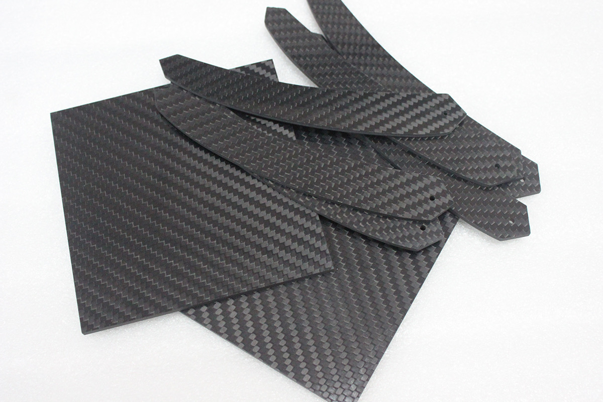
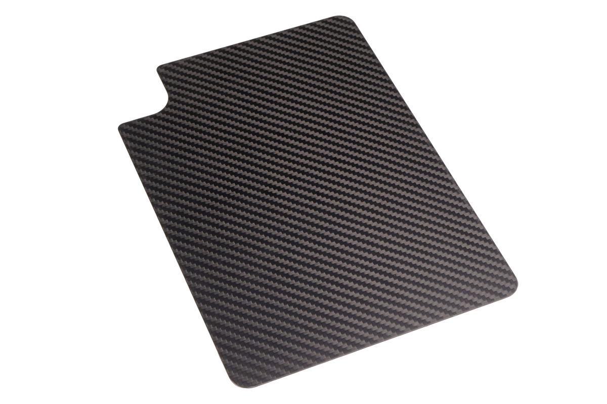
Flat stock and cut blanks for panels, frames, tooling plates and equipment structures.
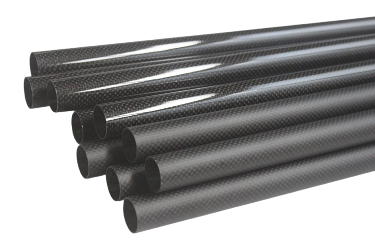
Custom Carbon Fiber SheetsLinear component forms for supports, links and buyer-designed assemblies with defined end interfaces.
Carbon Fiber Rods and TubesDrawing-based contours, holes, slots and cut-outs for mounting and mechanical interfaces.
Carbon Fiber CNC Machining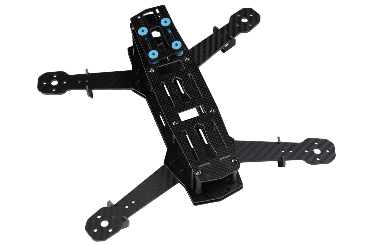
Project-specific parts reviewed around geometry, surface, interfaces, sample criteria and expected quantity.
Discuss a custom componentA controlled workflow keeps engineering assumptions, sample criteria and commercial scope visible.
Share the current 2D drawing, available 3D model, revision, part function and critical interfaces.
Review sheet, plate, rod, tube or custom construction against load direction, surface and environment.
Where appropriate, confirm prototype quantity and the dimensional, assembly and system checks controlled by the buyer.
After approved requirements are documented, confirm recurring quantity, inspection, identification and packaging scope.
The existing factory audit information supports the manufacturing context presented on the homepage. Cutting, molding, grinding, CNC and spraying are documented as in-house process categories.
For a robotics order, product-specific acceptance still comes from the drawing, quotation, approved sample and agreed inspection criteria—not from a general website capability statement.
These questions help procurement and engineering teams prepare comparable quotation inputs without assuming unsupported specifications.
Examples include arm plates, links, tooling supports, gripper components, sensor mounts, AGV panels and other drawing-defined parts. Feasibility is confirmed from the specific design.
Send the current 2D drawing and any available 3D model. Identify which document controls dimensions, tolerances and revision status, and confirm accepted file formats with the team.
Custom outlines, holes, slots and cut-outs can be reviewed. The drawing should identify datums, fastener interfaces, edge requirements and visible faces.
A prototype stage can be discussed when appropriate. Define what the sample must validate and do not assume that prototype completion equals approval for recurring production.
MOQ can depend on material form, geometry, machining, setup, tooling and commercial scope. No universal number is published because it must be confirmed in the quotation.
Provide drawings, component function, material assumptions, dimensions, quantity, surface requirements, critical interfaces, inspection needs, destination and target timing.
Include the component function, CAD revision, critical interfaces, prototype quantity and expected production quantity.
Robotics component RFQ
Share the drawing, component function, dimensions, quantity and application context for a factory-direct review.